3 relays, each with 4 contact sets (3NO + 1NC or Change-over type), 5A
Power supply unit
Input voltage: 85 – 265 V AC, Output voltage: 24 V DC, short-circuit-proof: 1 No
Carrier for mounting components such as PB & relay box
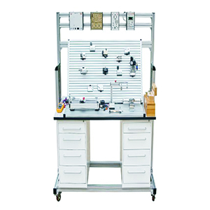
DRAWER SPECIFICATIONS
One pedestal drawer unit with 5 drawers, each with handles and individual locks Full metallic panel drawer slides
Drawer size
L 460 mm x W 495 mm x H 158 mm
Overall drawer unit size
L 470 mm x W 495 mm x H 825 mm
Drawer slide height
Approx. 85 mm
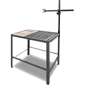
WORK TABLE SPECIFICATIONS
Aluminium profile legs (40 sq mm)
Wooden work surface
Dimensions: L-1200 mm x W-900 mm x H-900 mm
Includes four castor wheels (two lockable wheels at the front)
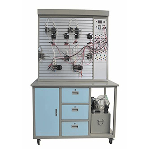
Vertical profile plate (Anodized Aluminium): 1100 mm x 700 mm
Includes carriers, mounting frames, and accessories
Components can be easily removed from the profile plate using an Allen key
All components are operational to demonstrate pneumatic circuits and principles. Each pneumatic component features a push-pull connector for various pneumatic circuit configurations.
Simulation software is provided to understand the working principles, symbols, and circuits.
Every pneumatic component having pneumatic push pull connector on it so that it can perform various pneumatic circuits with different connections.
ACCESSORIES
Tool Kit
Necessary PU pipes
Push-pull connectors
THE MACHINE ALSO CAN BE SUPPLY AS PER CUSTOMER REQUIREMENTS
UTILITY & CARPET AREA NEEDED FOR INSTALLATION
Approx. Carpet Area Needed: 7 x 5 (feet)
Power Supply Needed: Plug Socket, 230 Volt AC, 10 A. Single Phase Supply - 02 Nos.

Reviews
There are no reviews yet.